Logistics Automatic Weighing Solution
Overall Design Guide
Providing standardized automatic weighing system design, selection, and implementation specifications for logistics parks, factories, highway toll stations, and overload inspection stations. Covering full lifecycle management from system architecture to construction acceptance.
System Overview
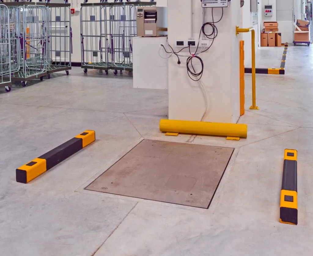
The logistics automatic weighing system is an integrated solution combining hardware and software, aimed at automating vehicle cargo weighing and data management. The system integrates weighing sensors, weighing instruments, scale structures, and data transmission devices to convert physical "weight data" into manageable digital information.
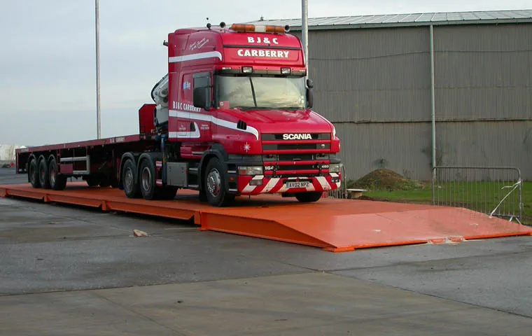
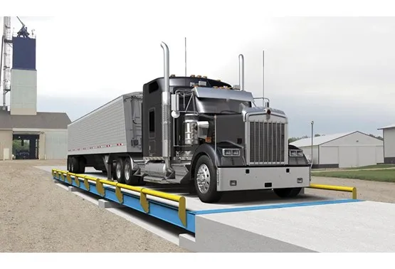
Static Weighing
Suitable for logistics parks, factories, etc., with high precision measurement (error ≤0.1% FS)
Dynamic Weighing
Suitable for highway toll stations, overload inspection stations, with fast response (≤0.5 seconds)
Axle Load Weighing
Used for bridge weight limits or road management, calculating total weight by summing axle weights
Whole Vehicle Weighing
Direct measurement of total vehicle weight, simple operation, suitable for logistics parks or parking lots
System Architecture
The system adopts a layered architecture design to ensure high availability and scalability:
L1 Perception and Execution Layer
Front-end devices such as weighing sensors, scale structures, and weighing instruments
L2 Edge Computing Layer
On-site servers/gateways responsible for offline verification and device control
L3 Cloud Service Layer
Core business logic, data management, and report analysis
Main Functions
Automatic Weighing
Supports static/dynamic weighing, automatically collects vehicle weight data
Real-time Monitoring
Millisecond-level device status reporting, automatic fault alarms
Data Management
Supports real-time data transmission, printing, cloud storage, and system integration
Report Analysis
Generates weighing reports, statistical analysis, assists operational decision-making
System Composition and Working Principle
In-depth analysis of the hardware and software architecture, core component functions, and data flow logic of the logistics automatic weighing system
System Architecture
The system adopts a layered architecture design, from bottom to top: Perception and Execution Layer (hardware), Edge Computing Layer (on-site server/gateway), Cloud Service Layer (core business), and Application Presentation Layer (management terminal).
Components and Functions
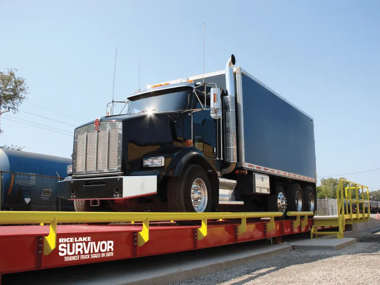
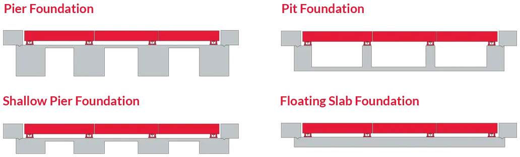
Scale Structure
Made of Q235B/Q345B steel, with hot-dip galvanizing or epoxy coating for corrosion protection. Panel thickness ≥10mm, U-beam thickness 3-8mm. Modular design facilitates transportation and installation.
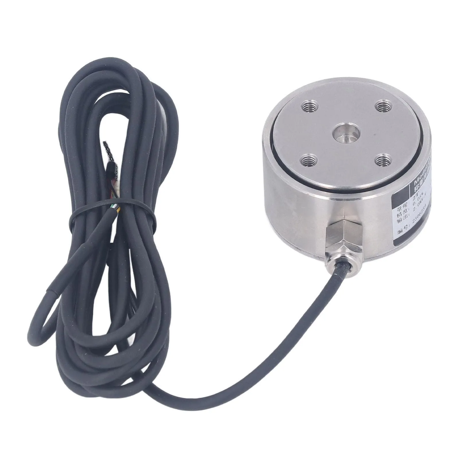
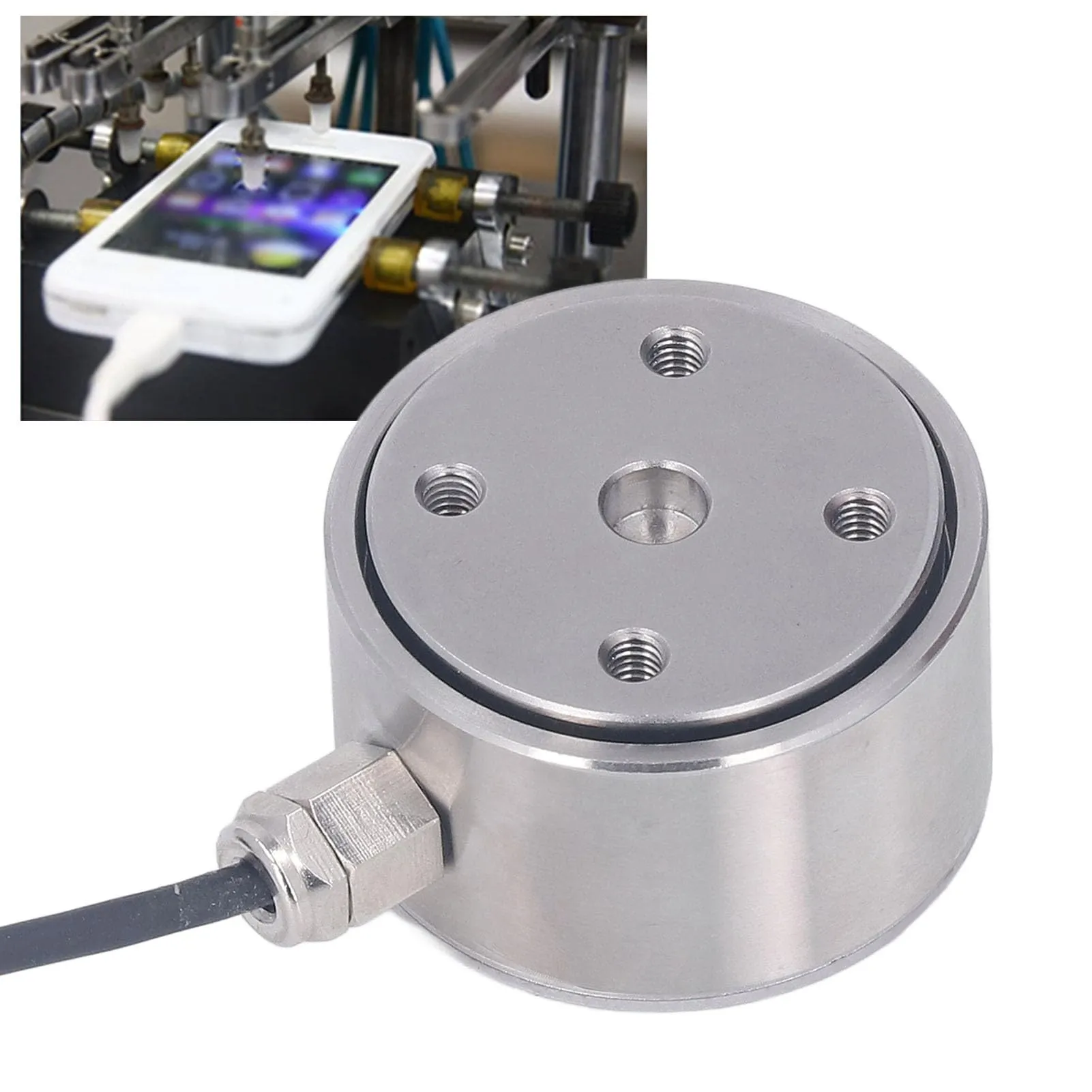
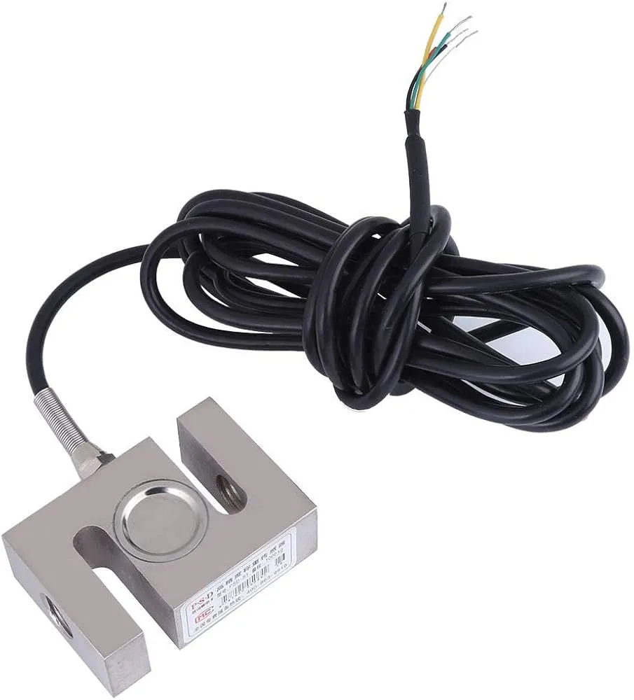
Weighing Sensor
Strain gauge sensors suitable for static weighing with 0.01% FS accuracy; piezoelectric sensors suitable for dynamic weighing with millisecond response. Rated load should be 120%-150% of actual maximum load.
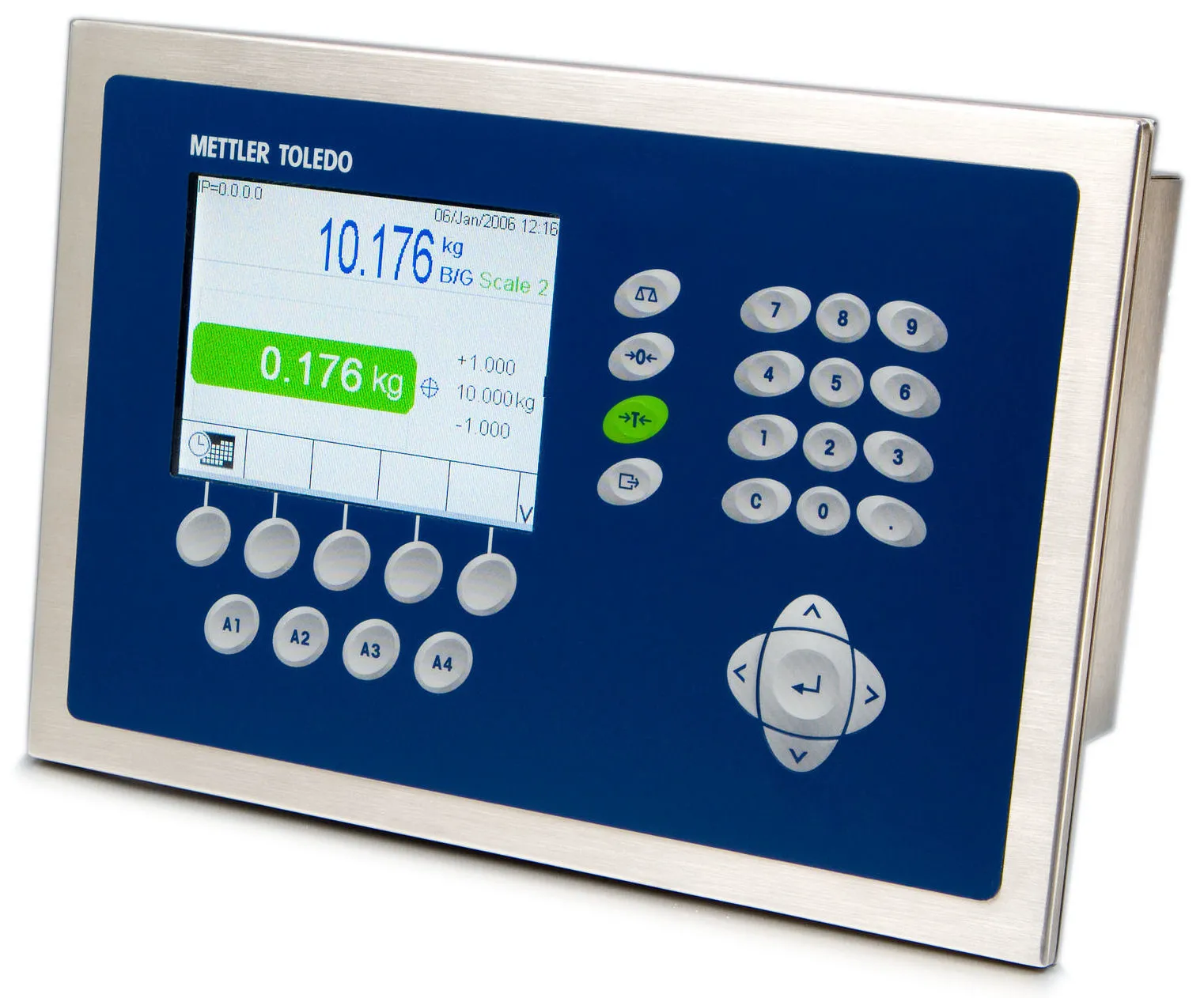
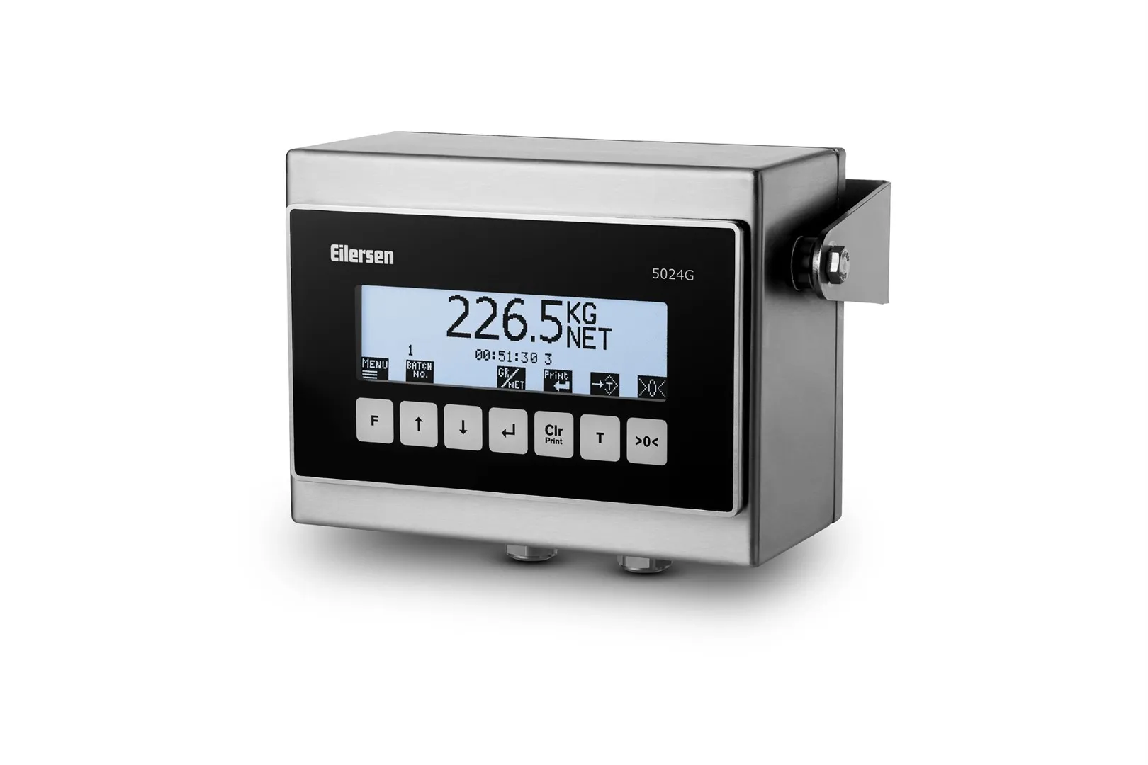
Weighing Instrument
Resolution at least 0.1 ton display accuracy. Interfaces: RS-485, Ethernet, 4G wireless transmission. Protection level IP65 or higher.
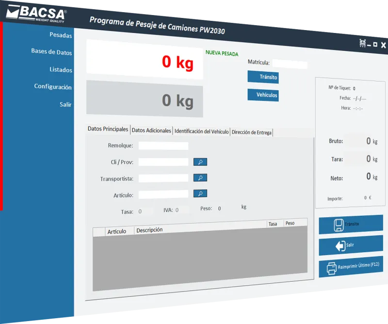
Weighing Management Software
Supports local deployment or cloud platform (cloud platform can manage multiple truck scales). Provides real-time data collection, report generation, historical query, and other functions.
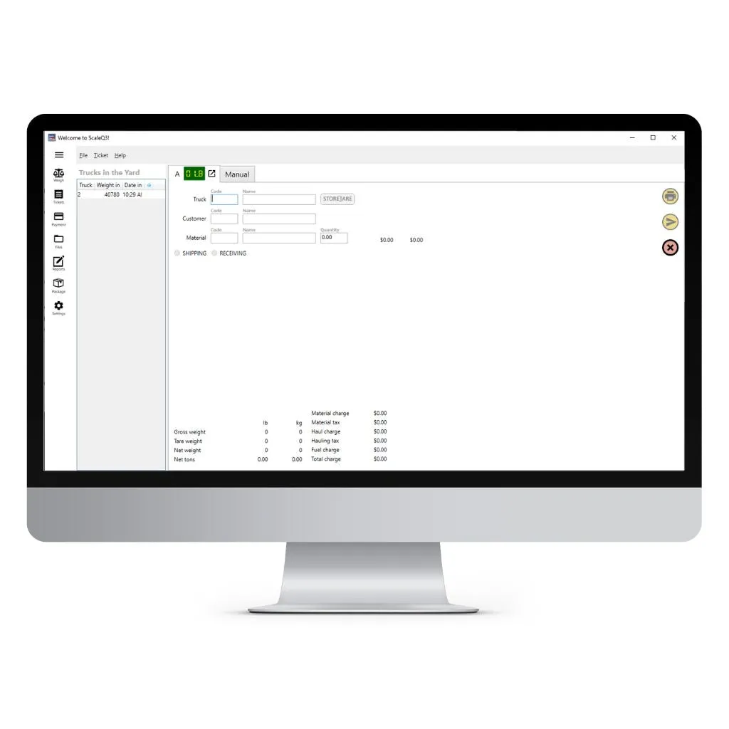
Ticket Management System
Automatically generates weighing tickets, supports custom templates. Seamlessly integrates with ERP, WMS, and other logistics management systems.
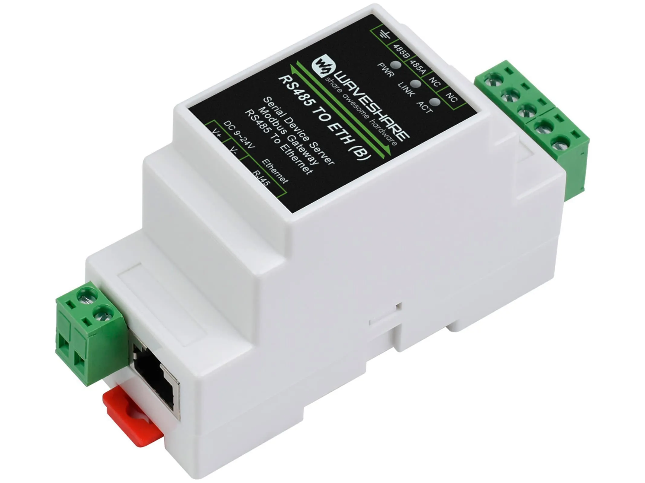
Data Transmission Module
RS-485 conversion module for short-distance transmission (<1200 meters), supports up to 32 devices connected. For long distances, Ethernet or 4G wireless transmission can be used.
Printing Equipment
Thermal printers suitable for fast printing and high-volume scenarios; dot matrix printers suitable for high-quality report printing. Interfaces must match data transmission subsystem.
Working Principle
The standard weighing process (Happy Path) is as follows:
Working Principle Explanation
When the vehicle drives onto the scale platform, the weighing sensor converts mechanical force into electrical signals. The weighing instrument amplifies, filters, and A/D converts the signal, then transmits data to the management software via RS-485 or Ethernet. The software processes, stores data, generates reports, and can trigger the printer to output weighing tickets.
Design Essentials
System design principles, key consideration dimensions, and core selection logic
Design Principles and Basis
Function Requirement Matching Principle
Design the system based on weighing type (static/dynamic/axle load/whole vehicle), weighing range and accuracy requirements, and data management needs.
Technical Parameter Selection Principle
Match sensor type and capacity, instrument functions and protection level, scale materials and structural design to actual working conditions.
Simplified Maintenance Principle
Modular design facilitates replacement of damaged parts, plug-and-play sensor design, supports remote diagnosis and firmware updates.
Scalability and Compatibility Principle
Reserve 20% redundant interfaces (RS-485 channels, I/O ports), support common protocols such as Modbus, TCP/IP.
Importance and Suggestions of Design Essentials
Good system design is the foundation of project success. Fully considering each essential point during the design phase can effectively reduce implementation risks, minimize rework costs, and improve system reliability and user satisfaction.
Design Suggestions
It is recommended to conduct thorough on-site surveys during the design phase to understand actual working conditions (environmental temperature and humidity, electromagnetic interference, foundation bearing capacity, etc.) and communicate fully with users about business requirements to ensure feasibility and applicability of the design solution.
Core Design/Selection Logic
The core design logic of this solution follows the principles of "demand-driven, performance-first, cost-controllable":
- First clarify weighing type and accuracy requirements to determine sensor type
- Determine sensor capacity based on maximum weighing range (120%-150% safety margin)
- Select protection level and materials according to environmental conditions
- Choose software functions and interface configurations based on data management needs
- Optimize solution considering total lifecycle cost
Key Consideration Dimensions
| Dimension | Key Indicators | Design Suggestions |
|---|---|---|
| Performance and Experience | Weighing accuracy, response speed, ease of operation | Static weighing error ≤0.1% FS, dynamic weighing error ≤0.5% FS, response time ≤0.5 seconds |
| Stability/Reliability | MTBF, failure rate, environmental adaptability | MTBF ≥50000 hours, operating temperature -10°C~40°C, humidity 40%-60% |
| Maintainability/Replaceability | Modularity, ease of maintenance | Modular design, plug-and-play sensors, support remote diagnosis |
| Compatibility/Scalability | Interface standards, protocol support, expansion capability | Support Modbus/TCP-IP protocols, reserve 20% redundant interfaces |
| Lifecycle Cost (LCC) | Procurement cost, operation and maintenance cost, replacement cost | Consider total cost of ownership over 10-year usage cycle |
| Energy Consumption/Environmental Protection | Power consumption, material environmental compliance | Use low-power devices, materials comply with RoHS requirements |
Application Scenarios
Scope of application and typical sub-scenario analysis of logistics automatic weighing systems
Scope of Application
The logistics automatic weighing system is widely used in various scenarios requiring vehicle or cargo weight measurement, mainly including: logistics parks, factories, ports and docks, highway toll stations, overload inspection stations, mining quarries, waste treatment plants, agricultural product collection stations, etc.
Typical Sub-Scenarios
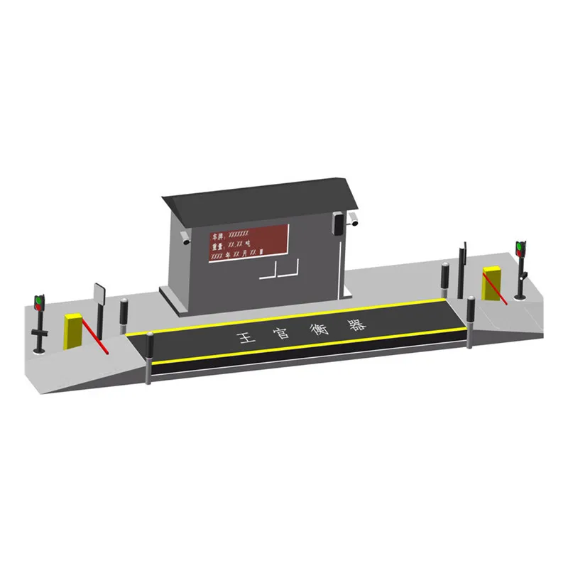
Scenario 1: Logistics Park
Business Characteristics: High traffic volume, requires fast weighing and ticket printing
Environmental Constraints: Outdoor environment, needs rain and dust protection
Key Risks: Queue congestion during peak hours
Design Focus: High throughput, high automation
Scenario 2: Factory Enterprise
Business Characteristics: Raw material inbound and finished product outbound weighing
Environmental Constraints: Possible dust and corrosive gases
Key Risks: Measurement disputes
Design Focus: High precision, anti-cheating
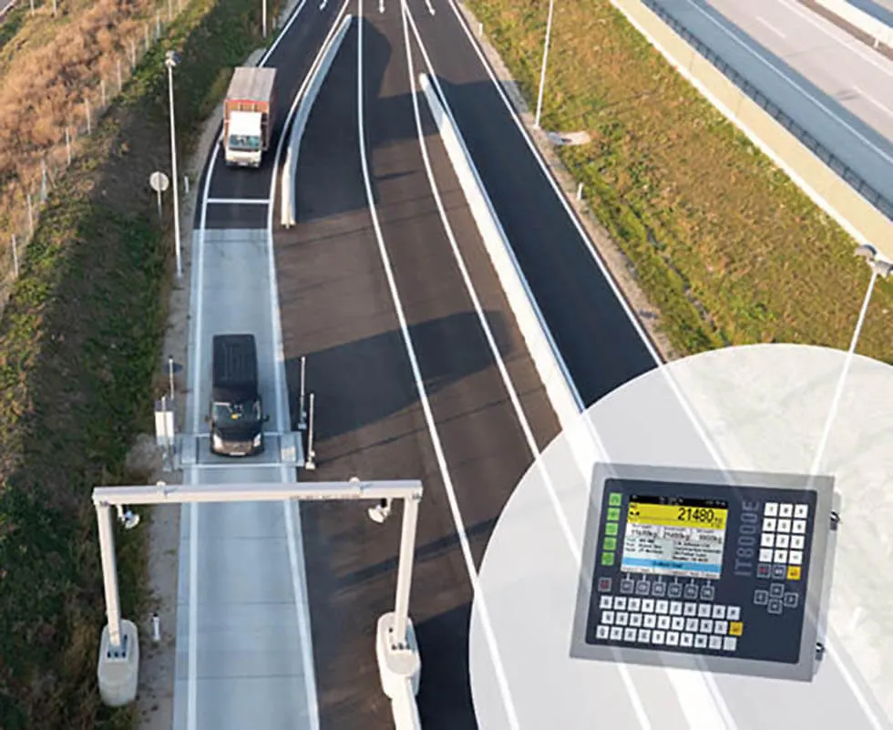
Scenario 3: Highway Toll Station
Business Characteristics: Dynamic weighing, non-stop measurement
Environmental Constraints: All-weather operation, high vehicle speed
Key Risks: Insufficient dynamic accuracy
Design Focus: Fast response, impact resistance
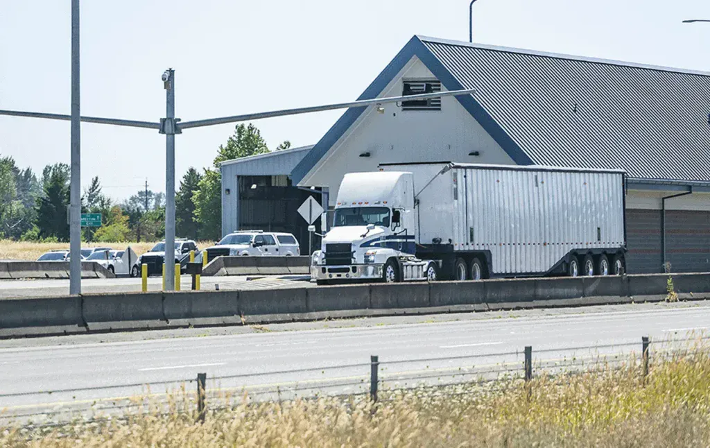
Scenario 4: Overload Inspection Station
Business Characteristics: Law enforcement inspection, requires high credibility
Environmental Constraints: Roadside environment, requires protective facilities
Key Risks: Disputes over inspection results
Design Focus: Legal metrology certification
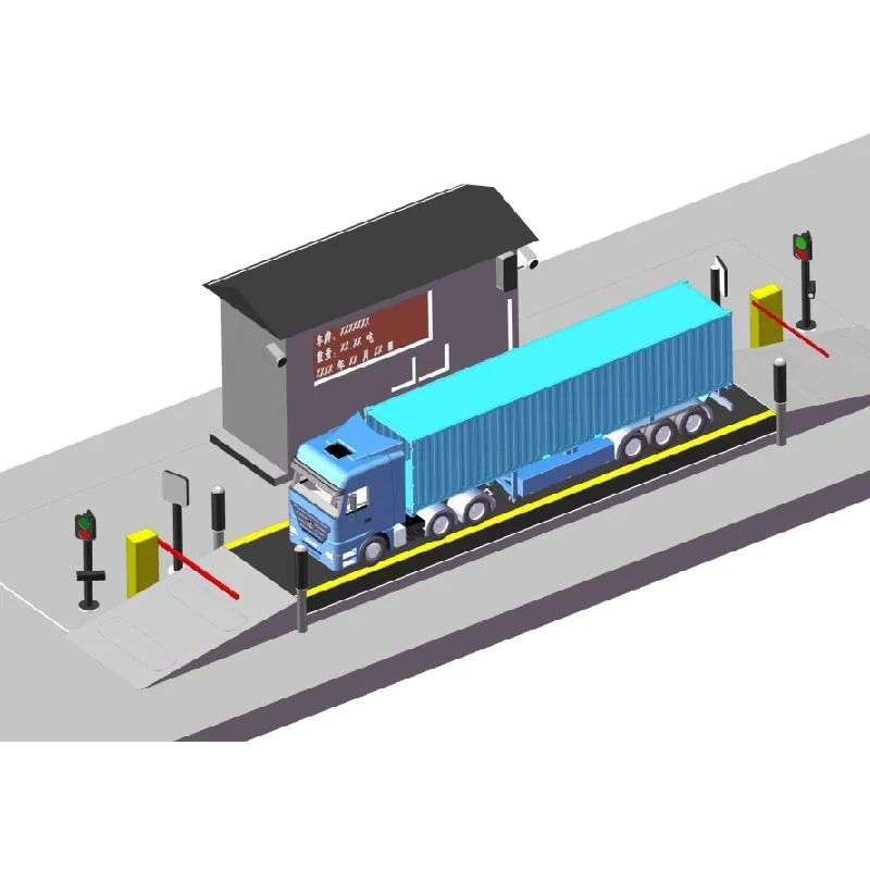
Scenario 5: Port Dock
Business Characteristics: Container weighing, large tonnage
Environmental Constraints: Salt spray corrosion, humidity
Key Risks: Equipment corrosion failure
Design Focus: Corrosion resistance, large range
Scenario 6: Mining Quarry
Business Characteristics: Ore transport weighing, heavy-duty vehicles
Environmental Constraints: High dust, strong vibration
Key Risks: Sensor damage
Design Focus: Impact resistance, dustproof
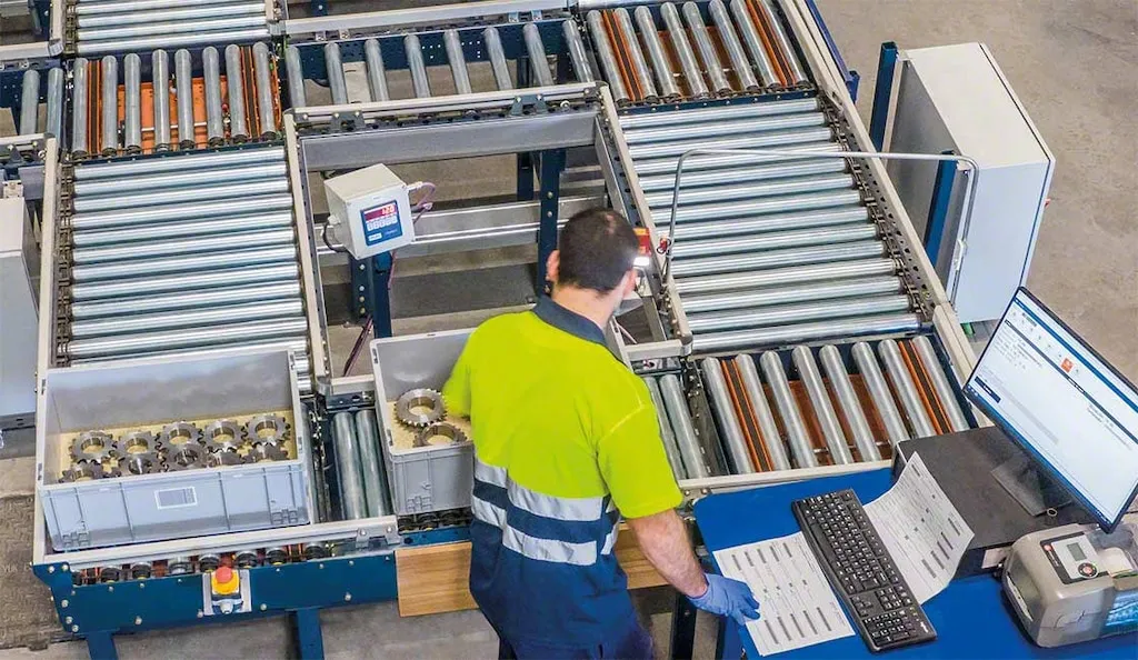
Scenario 7: Warehouse Logistics Center
Business Characteristics: Cargo sorting weighing, integrated with WMS
Environmental Constraints: Indoor environment, limited space
Key Risks: System integration issues
Design Focus: Interface compatibility, compact design
Scenario 8: Express Sorting Center
Business Characteristics: Fast weighing of small items, high frequency
Environmental Constraints: Automated assembly line
Key Risks: Weighing speed bottleneck
Design Focus: High-speed dynamic weighing
Scenario Selection Considerations
Different application scenarios have significant differences in system requirements. When designing solutions, it is necessary to fully understand scenario characteristics and select appropriate equipment configurations and technical solutions. Environmental factors (temperature, humidity, dust, corrosion, etc.) have important impacts on equipment selection.
Solution Selection
Technical route analysis, solution comparison, and product selection guide
Solution Comparison
| Solution Type | Applicable Scenarios | Advantages | Disadvantages |
|---|---|---|---|
| Static Weighing Solution | Logistics parks, factories | High accuracy (≤0.1% FS), good stability | Requires vehicle stop, lower efficiency |
| Dynamic Weighing Solution | Highway toll stations, inspection stations | Weighing without stopping, high efficiency | Relatively lower accuracy (≤0.5% FS) |
| Axle Load Weighing Solution | Bridge weight limits, road management | Detects axle load distribution, overload identification | Complex equipment, higher cost |
| Portable Weighing Solution | Temporary inspection, mobile law enforcement | Flexible and portable, quick deployment | Limited range, average accuracy |
Technical Route Analysis and Selection Basis
Sensor Technical Routes
| Sensor Type | Working Principle | Accuracy | Response Speed | Applicable Scenarios |
|---|---|---|---|---|
| Strain Gauge Sensor | Electrical resistance strain effect | 0.01% FS | Medium | Static Weighing |
| Piezoelectric Sensor | Piezoelectric effect | 0.1% FS | Millisecond level | Dynamic Weighing |
| Capacitive Sensor | Capacitance change | 0.05% FS | Fast | High-precision scenarios |
Technical Indicator Thresholds and Recommended Ranges for Product Selection
Weighing Sensor Technical Indicators
| Indicator Name | Recommended Range/Level | Impact on System | Acceptance/Test Method |
|---|---|---|---|
| Rated Capacity | 120%-150% of actual maximum load | Too small causes damage, too large affects accuracy | Standard weight loading test |
| Total Error | ≤0.02% FS (static) | Directly affects weighing accuracy | Standard weight calibration |
| Sensitivity | 2.0±0.1 mV/V | Affects signal output strength | Instrument measurement |
| Protection Level | ≥IP67 | Affects environmental adaptability | Protection level test |
| Operating Temperature | -30°C ~ +70°C | Affects environmental applicability | Temperature cycling test |
Weighing Instrument Technical Indicators
| Indicator Name | Recommended Range/Level | Impact on System | Acceptance/Test Method |
|---|---|---|---|
| Display Resolution | ≥1/30000 | Affects display accuracy | Function test |
| A/D Conversion Rate | ≥10 times/second | Affects dynamic response | Instrument measurement |
| Communication Interface | RS-485/Ethernet/4G | Affects data transmission method | Interface test |
| Protection Level | ≥IP65 | Affects environmental adaptability | Protection level test |
Scale Structure Technical Indicators
| Indicator Name | Recommended Range/Level | Impact on System | Acceptance/Test Method |
|---|---|---|---|
| Steel Grade | Q235B/Q345B | Affects structural strength | Material certification inspection |
| Panel Thickness | ≥10mm | Affects load capacity | Dimension measurement |
| U-beam Thickness | 3-8mm | Affects structural stiffness | Dimension measurement |
| Corrosion Protection | Hot-dip galvanizing/Epoxy coating | Affects service life | Coating thickness measurement |
| Overload Protection | 1.5 times rated load | Affects safety | Overload test |
Solution Design
Typical interface introduction, device connection and wiring logic explanation
Typical Interface Introduction
| Interface Type | Transmission Distance | Transmission Rate | Applicable Scenarios |
|---|---|---|---|
| RS-485 | ≤1200 meters | 9600-115200 bps | Short distance, multi-device connection |
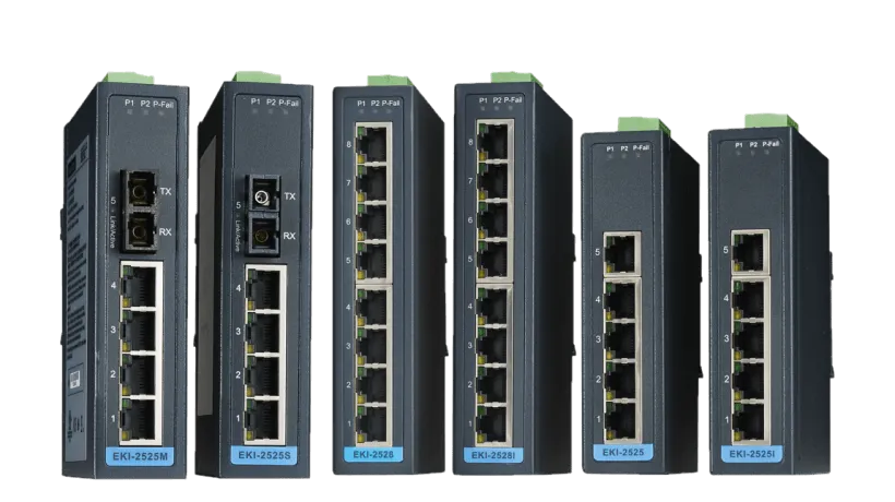
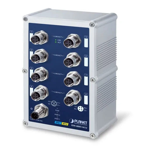
| Ethernet | ≤100 meters (single segment) | 10/100/1000 Mbps | High-speed data transmission |
| 4G Wireless | Unlimited | ≤100 Mbps | Remote transmission, mobile scenarios |
| USB | ≤5 meters | ≤480 Mbps | Local device connection |
Device Connection and Interface Design
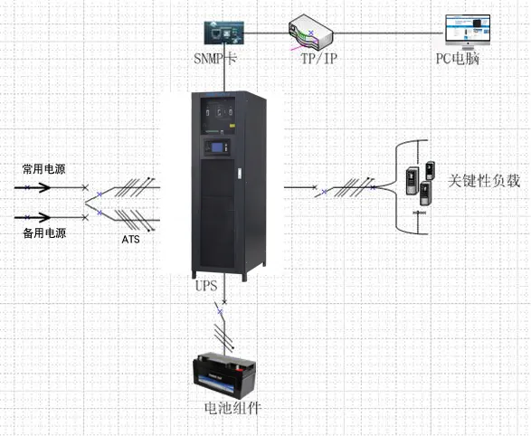
Typical System Connection Topology
Typical Wiring and Interface Logic Explanation
Sensor Wiring Instructions
Signal Cable: Power Cable YJLY-0.6/1kV-2/1.5mm²
Ground Cable: Power Cable VLV-0.6/1kV-1/4mm²
Sensor signal cables should be laid separately from power cables to avoid electromagnetic interference. Shielded cables are recommended, with the shield grounded at one end.
Sensor → Junction Box
Multiple sensor signals are paralleled through the junction box for signal aggregation and adjustment. The junction box should have waterproof and dustproof functions (IP65 or above).
Junction Box → Instrument
Use RS-485 or analog signal transmission. RS-485 transmission distance can reach 1200 meters, supporting multiple instruments cascading.
Instrument → Host Computer
Connected via Ethernet or RS-485. Ethernet is suitable for high-speed data transmission and remote access, RS-485 is suitable for simple scenarios.
Host Computer → Printer
Connected via USB or Ethernet. Network printers are recommended for multi-terminal sharing.
Risk Assessment
Risk identification, assessment criteria, and response strategies
Risk Identification
Technical Risks
Risks related to technical implementation, system design, and technology selection. Including: sensor accuracy not meeting standards, software compatibility issues, communication protocol mismatches, etc.
Operational Risks
Risks encountered during system use or maintenance. Including: insufficient operator training, untimely maintenance, misoperation, etc.
Environmental Risks
Risks related to environmental factors. Including: temperature exceeding limits, high humidity, electromagnetic interference, dust corrosion, etc.
Legal and Compliance Risks
Risks involving non-compliance with laws and regulations. Including: measuring instruments not verified, data storage not meeting regulations, etc.
Supply Chain Risks
Risks from suppliers, material supply, external partners. Including: equipment delivery delays, spare parts shortages, supplier bankruptcy, etc.
Safety Risks
Potential risks in network security, personal safety, data security, etc. Such as system intrusion, data leakage, equipment causing injury, etc.
Risk Assessment Criteria
Risk Response Strategies
| Strategy Type | Description | Applicable Scenarios |
|---|---|---|
| Avoidance | Avoid risk occurrence by changing design, process, or workflow | High probability, high impact risks |
| Mitigation | Take preventive measures to reduce risk probability or impact | Medium risks |
| Transfer | Transfer risk to third parties (e.g., insurance, outsourcing) | External risks difficult to control |
| Acceptance | Accept risk under cost or other constraints, but have contingency plans | Low probability, low impact risks |
Emergency Plans and Response Measures
Emergency Response
Take measures promptly after risk occurrence to reduce losses. Establish 24-hour duty system to ensure timely fault response.
Risk Monitoring and Management
Regularly assess and monitor various risks in the project to ensure timely detection and handling of potential issues. Monthly risk assessment meetings are recommended.
Responsibility Allocation
Assign responsible persons for each risk to ensure timely response and implementation of plans. Clarify risk management responsibilities for each position.
Spare Parts Inventory
Reserve a certain quantity of spare parts for key equipment (sensors, instruments) to ensure quick replacement in case of failure.
Supporting Systems
System supporting requirements, cross-disciplinary interface requirements, and integration solutions
System Supporting Requirements
The normal operation of the logistics automatic weighing system requires support from multiple supporting systems, including power supply system, network communication system, environmental control system, etc. The design quality of these supporting systems directly affects the stability and reliability of the main system.
Cross-disciplinary Interface Requirements and Integration
Key Points for Cross-disciplinary Coordination
The implementation of the weighing system involves multiple disciplines such as civil engineering, electrical, network, and software. Interface requirements for each discipline need to be clarified at the project initiation to ensure smooth system integration.
Supporting Systems Introduction
UPS System
Provides uninterruptible power protection for key equipment. It is recommended to configure 15-30 minutes backup time to ensure data safety and normal shutdown during power outages.
Power Distribution System
Provides stable power supply. Voltage fluctuation range should be controlled within ±10% of rated voltage (198-242V for 220V equipment).
Lightning Protection and Grounding System
Protects equipment from lightning damage. Ground resistance should be ≤4Ω, and surge protectors should be installed on signal lines.
Air Conditioning System
Controls temperature and humidity in equipment rooms. Operating temperature -10°C~40°C, relative humidity 40%-60%.
Fire Protection System
Gas fire extinguishing systems should be installed in equipment rooms to avoid water damage. Smoke detectors should be linked with the fire alarm system.
Structured Cabling
Standardized cabling system ensures signal transmission quality. Separate strong and weak currents, use shielded cables for signal lines.
Interface List
| Interface ID | Interface Name | Interface Type | Responsible Party | Remarks |
|---|---|---|---|---|
| IF-001 | Power Interface | AC 220V/50Hz | Electrical Discipline | With Grounding |
| IF-002 | Network Interface | RJ45 Ethernet | Network Discipline | Gigabit Network |
| IF-003 | Foundation Embedment | Concrete Foundation | Civil Engineering | Construct as per drawings |
| IF-004 | Drainage Interface | DN100 Drain Pipe | Water Supply and Drainage | Scale Pit Drainage |
| IF-005 | Data Interface | API/Database | Software Discipline | Integration with ERP/WMS |
Tools and Accessories
Accessory list, installation tools, and accessory list
Accessory List
| No. | Accessory Name | Specification/Model | Quantity | Purpose |
|---|---|---|---|---|
| 1 | Weighing Sensor | Selected according to range | As per design | Weight detection |
| 2 | Weighing Instrument | Digital instrument | 1 unit per weighing point | Signal processing and display |
| 3 | Junction Box | 4-8 channels | 1 per scale platform | Signal aggregation |
| 4 | Printer | Thermal/Dot matrix | 1 unit per weighing point | Ticket printing |
| 5 | Industrial PC | Industrial-grade PC | 1 unit per weighing point | Data processing |
Installation Tools

Level
Used for checking the levelness during scale platform installation to ensure flat installation. Accuracy requirement: 0.02mm/m.
Multimeter
Used for electrical circuit testing and sensor signal measurement. Digital multimeter with accuracy ≥0.5% is recommended.
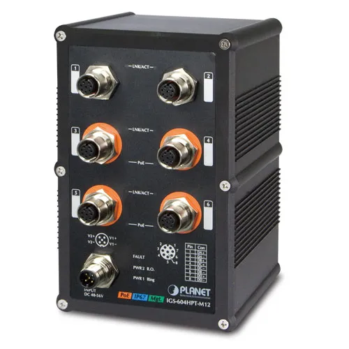
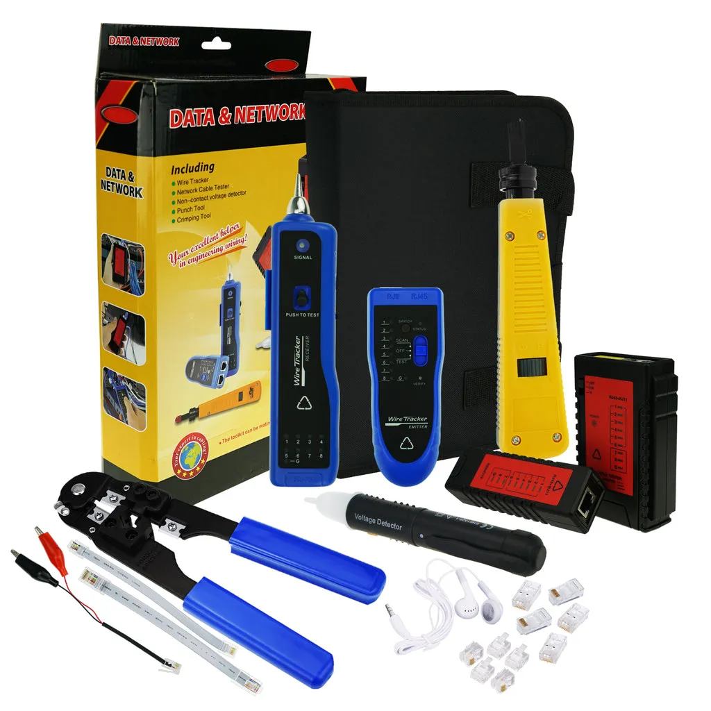
Network Tester
Used for network cable testing and continuity checking. Supports RJ45 interface testing.
Torque Wrench
Used for tightening sensor installation bolts, ensuring torque meets requirements. Range: 10-100N·m.
Cable Wiring Tools
Used for cable laying and conduit work. Includes wire pullers, cable cutters, etc.
Laser Rangefinder
Used for installation positioning and dimension measurement. Measurement range: 0.05-100m, accuracy ±1.5mm.
Accessory List
| No. | Accessory Name | Specification/Model | Purpose |
|---|---|---|---|
| 1 | Signal Cable | YJLY-0.6/1kV-2/1.5mm² | Sensor signal transmission |
| 2 | Ground Cable | VLV-0.6/1kV-1/4mm² | Equipment grounding protection |
| 3 | Network Cable | CAT6 Shielded Cable | Data communication |
| 4 | Wire Duct/Conduit | PVC/Galvanized Steel Pipe | Cable protection |
| 5 | Waterproof Connector | IP67 Waterproof Rating | Outdoor wiring protection |
| 6 | Cable Ties/Clamps | Nylon Cable Ties | Cable fixing |
Quality Control
Product quality differentiation, potential issues, and quality control measures
Product Quality Differentiation
| Quality Dimension | High-Quality Product Features | Low-Quality Product Features |
|---|---|---|
| Network Security | Supports encrypted communication, access control, security audit | No encryption, default passwords, no logs |
| Chip Processing Capability | Industrial-grade chips, high-speed A/D conversion, good stability | Consumer-grade chips, slow conversion speed, prone to crashes |
| Hardware Materials | High-quality stainless steel, high-precision strain gauges | Ordinary steel, low-precision strain gauges |
| Craftsmanship | Precision machining, strict sealing, solid welding | Rough machining, poor sealing, weak welds |
| Protection Level | IP67/IP68, corrosion-resistant treatment | Below IP54, prone to rust |
Potential Issues and Risks of Poor Quality
Quality Risk Warning
Using low-quality products may cause serious problems such as weighing accuracy not meeting standards, frequent equipment failures, increased maintenance costs, safety hazards, and measurement disputes.
Accuracy Drift
Low-quality sensors have poor temperature compensation, causing severe accuracy drift with environmental changes, leading to inaccurate weighing data.
Equipment Failure
Poor quality components have short lifespan and high failure rates, affecting system availability and business continuity.
Safety Hazards
Insufficient protection level leads to electric leakage risks; network security vulnerabilities may be exploited for data tampering.
Maintenance Costs
Frequent repairs and replacements increase operation and maintenance costs, affecting return on investment.
Quality Control Measures and Recommended Practices
- Select suppliers with relevant certifications (ISO9001, metrology instrument licenses, etc.)
- Require suppliers to provide product test reports and quality certificates
- Conduct incoming inspection to verify product specifications and appearance quality
- Perform functional tests before installation to confirm normal equipment operation
- Establish quality traceability mechanism, record equipment serial numbers and installation information
- Regularly calibrate and maintain to ensure continuous compliance with accuracy requirements
Calculation Tools
System capacity, link redundancy, network performance, and power demand calculations
Sensor Quantity Calculation
System Capacity Calculation
Network Bandwidth Calculation
Power Demand Calculation
Weighing Accuracy Verification Calculation
Installation and Commissioning
Pre-installation requirements, construction specifications, and commissioning methods
Pre-installation Requirements
Site Survey Considerations
Site Levelness
The installation site needs to be sufficiently level. Uneven ground causes uneven force on the scale platform when vehicles weigh, affecting weighing accuracy.
Foundation Bearing Capacity
The foundation should have sufficient bearing capacity. A 200-ton truck scale requires the foundation to support the vehicle, cargo, and scale self-weight. Insufficient bearing capacity leads to foundation settlement.
Drainage Design
The foundation should have good drainage design to avoid water accumulation damaging the scale and foundation. The scale pit should have drainage ditches and sumps.
Power Supply Conditions
Voltage fluctuation range should be within ±10% of rated voltage. For 220V equipment, voltage should be between 198-242V. UPS configuration is recommended.
Risk Points
Installation Risk Tips
1. Poor foundation construction quality causing later settlement
2. Inaccurate sensor installation position affecting accuracy
3. Non-standard cable laying causing signal interference
4. Poor grounding causing equipment damage or safety hazards
Installation Requirements
- Ensure foundation levelness and bearing capacity; use appropriate formwork and vibration equipment during concrete pouring
- Sensor installation position should be precise, installed at suitable positions under scale support beams to ensure uniform force
- Device wiring should be laid separately to prevent signal interference; shielding measures should be considered
- All equipment should be reliably grounded, with grounding resistance ≤4Ω
Construction Specifications
| Construction Item | Specification Requirements | Acceptance Criteria |
|---|---|---|
| Foundation Pouring | C30 concrete, curing ≥28 days | Strength test passed |
| Scale Platform Installation | Levelness ≤3mm/m | Leveling instrument inspection |
| Sensor Installation | Verticality ≤1mm | Plumb line inspection |
| Cable Laying | Strong and weak currents separated by ≥300mm | On-site inspection |
| Grounding Construction | Ground resistance ≤4Ω | Ground resistance test |
Commissioning Methods and Precautions
Step 1: Appearance Inspection
Check if equipment appearance is intact, wiring is firm, and labels are clear.
Step 2: Power-on Test
After powering on, check if equipment starts normally, display is normal, and no abnormal alarms.
Step 3: Zero Calibration
Perform zero calibration in empty scale state to ensure display is zero.
Step 4: Range Calibration
Use standard weights for range calibration and adjust gain parameters.
Step 5: Accuracy Verification
Verify weighing accuracy using standard weights of different masses and record error data.
Step 6: Functional Test
Test if data transmission, printing, storage, and other functions work properly.
Safety and Prevention
Network Security
Enable access control and encrypted communication, regularly update passwords, and close unnecessary ports and services.
Personal Safety
Set warning signs during construction, power off for live work, and wear safety belts for high-altitude work.
Equipment Safety
Install lightning protection facilities, configure surge protectors, and ensure reliable grounding of equipment enclosures.
Data Security
Regularly back up data, set access permissions, and record operation logs.
Acceptance and Maintenance
Acceptance criteria, test items, and operation & maintenance requirements
Acceptance Criteria and Test Items
| Test Item | Test Method | Acceptance Criteria |
|---|---|---|
| Weighing Accuracy | Standard weight loading test | Static error ≤0.1% FS |
| Repeatability | Multiple weighings of the same weight | Repeatability error ≤0.05% FS |
| Off-center Error | Weights placed at different positions | Off-center error ≤0.1% FS |
| Data Transmission | Communication test | 100% data transmission accuracy |
| Printing Function | Printing test | Complete and clear print content |
| Software Function | Function test | All functions operate normally |
Operation and Maintenance Requirements
Daily Maintenance
- Check if the scale platform surface has debris and clean it timely
- Check if the display instrument works normally
- Check if the printer works normally and has sufficient paper
- Check if the network connection is normal
Periodic Maintenance
| Maintenance Item | Maintenance Cycle | Maintenance Content |
|---|---|---|
| Accuracy Calibration | Quarterly | Calibrate using standard weights and record calibration data |
| Sensor Inspection | Biannually | Inspect sensor appearance, wiring, and signal output |
| Scale Structure Inspection | Annually | Inspect scale structure, corrosion protection layer, and limit devices |
| Software Update | As needed | Update software versions and fix known issues |
| Metrology Verification | Annually | Mandatory verification by metrology department |
Version Records and Revision Notes
| Version | Date | Revision Content | Prepared By |
|---|---|---|---|
| v1.0.0 | 2026-01-04 | Initial version release | Solution Mall |
Document Explanation
This design guide provides a reference for the overall design of logistics automatic weighing systems. Actual project implementation should be adjusted according to specific scenarios and requirements. For questions, please contact the Solution Mall technical support team.